FM Drone Synth
This project was great fun to design and build: a 2-voice, 3-operator, fully analog, FM synthesizer. Using the 40106!
Though I call it a "drone synth" it's actually really good for hard kicks and harsh tones as well.
It also features stereo output, where voice 1 is assigned to the left channel and voice 2 to the right. This creates a wide
stereo effect which is great for those drone landscapes. It also features a switch to sync the two voices to do rhythmic stereo stuff.
A video on it can be found on
here.
The 40106 VCO
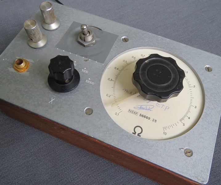
This synth is build around the 40106 hex inverter which features six schmitt trigger inverters.
It's a great little IC for building noise boxes (or fart boxes) though it is possible to
make a pretty decent linear or exponential VCO with very few additional components.
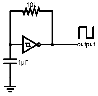
The most basic 40106 oscillator you can build only needs a single capacitor and (variable) resistor.
This will generate a square wave signal on the inverter output and a triangle-ish wave on the inverter input.
If you want to know the exact workings on this, just Google "40106 oscillator" and you'll find hundreds of
pages with explanation and neat things people have already build around this very simple circuit.
And you might've guessed that this also is the core of the FM Drone Synth. However I've done a couple things differently.
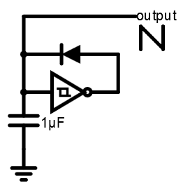
I've replaced the resistor with a diode, to change the inverter input waveform to a sawtooth waveform.
The shape changes because when the inverter output goes high it'll now charge the capacitor instantly, because of the low forward resistance of the diode.
Then when the inverter output switches to low (due to the voltage build up on the input) the capacitor discharges slowly through the inverter input.
On the inverter output you'll now find a very tiny pulse instead of a square wave. This pulse is great for triggering stuff ;)
The VCO:
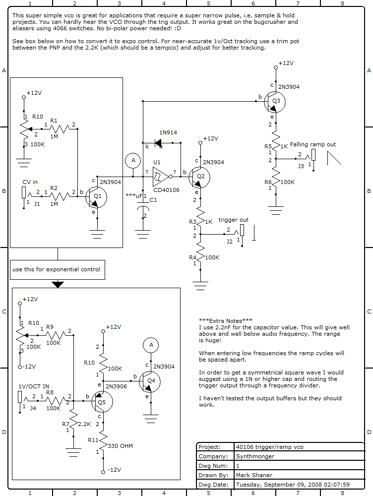
Now that I had the desired sawtooth oscillator I added an NPN transistor as a variable resistor of sorts, to control the discharge rate of the capacitor and thus
the frequency of the oscillator. Later I actually found a schematic on a "40106 VCO", created by one Mark Shaner, which is the exact same thing I had created, so I'm just going to
provide that schematic instead:
The Wierd FM Voice
Now that we have looked over the basics, here's the schematic of a single voice:
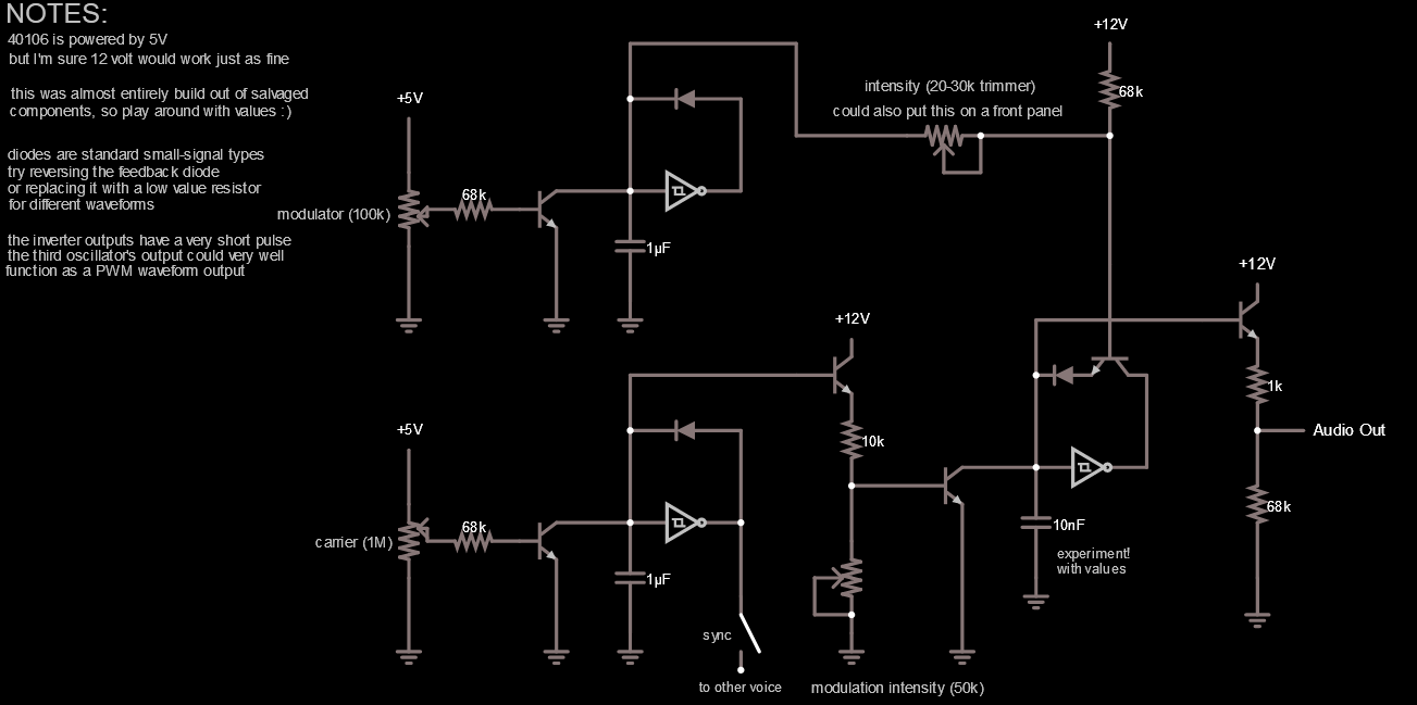
As you can see there are three 40106 sawtooth oscillators in this circuit, but they have different functionalities.
The top-left and bottom-left oscillators technically are both modulators for the bottom-right one, however I have setup the top-left one to be
a modulator and the bottom-left one to be a carrier on the front panel controls. This simply felt more intuitive the way the circuit behaved.
Both those oscillators affect the frequency of the bottom-right one though those NPN transistors (again they act as variable resistors of sorts), however the modulator also affects the waveform shape and can even make it
hang for a bit, creating more square-wave ish shapes.
I always build my creations out of salvaged/recycled parts, so some values (such as the 68k CV resistors) are a bit odd, but they worked really well given
the results I got. My advice is to experiment with resistor and capacitor values. Check the 40106 VCO schematic in the previous section for reference. I found those values work great as well.