The Korg Poly800 MK-III
This project was quite a doozy, but the results are more than worth it.
Youtube explanation and demo video:
watch it here.
Arduino project files:
download.
This page is a work-in-progress, there's a lot of ground to cover...
The project also isn't entirely finished yet.
Though it sounds really good and very much like a Poly800 I do still need to polish and update some aspects of it.
Please keep this in mind when basing your own projects off this one.
The Code
The firmware for this synth was entirely written in C in the Arduino IDE. I'm using two Atmega32a AVR microprocessors, one to act as the CPU
the other to emulate the DCO's.
The code can be downloaded
here.
Please keep in mind this is still a work-in-progress, so things may be a bit messy still.
Anyways, enough excuses let us take a look at the various things that needed emulating....
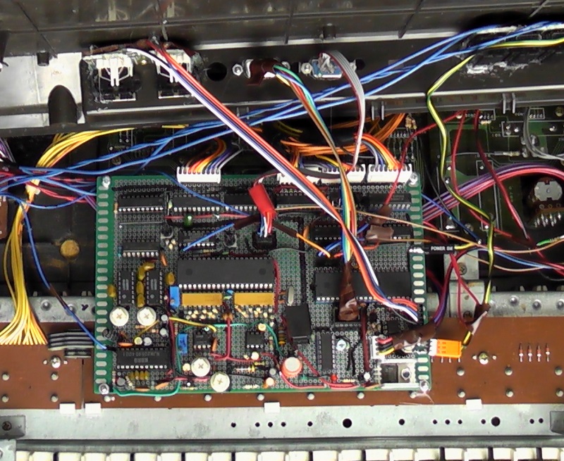
The "CPU" Atmega32:
This Atmega32a MCU acts as the main controller for everything in the MK-III, from scanning the keyboard matrix, to controlling the various latches and the 8-bit
data bus, to sending and receiving MIDI.
The "DCO" Atmega32:
This Atmega32a MCU is responsible for digitally emulating the Korg M5232 / OKI MSM5232RS 8-Channel Tone Generator IC. Well... with a few twists and turns.
It is connected to the "CPU" via the 8-bit bus and several "REG" control signals. The control signals basically act as "register select" controls, which are
very often found on old sound generator ICs and it makes control a bit faster.
The REG controls combined with the data bus make for a 10-bit bus together, so the many parameters of the "DCO" can be adressed, as well as note data.
Setting both REG controls to high and having data bus bit 7 high as well means the rest of the data bus bits are for note data.
Bit 6 tells the "DCO" if the data is NOTE ON or NOTE OFF, the remaining bits are the note number.
You may notice there's no pitch-bend or detuning data possible this way, that is because those things are done in the analog realm with a 4046's VCO:
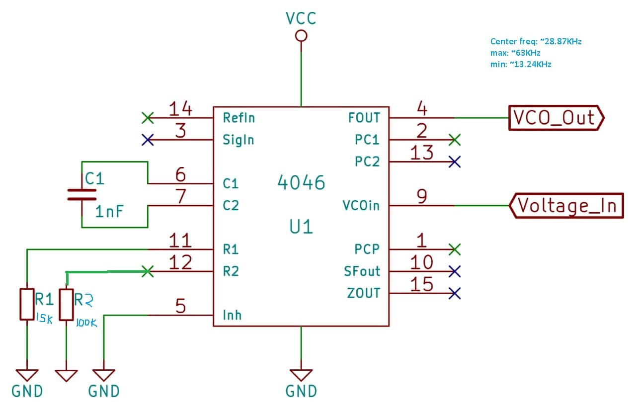
The output of the VCO connects directly to an external interrupt pin on the Atmega32.
Normally I use one of the Atmega's internal timers (usually Timer1 since it is 16-bit) to trigger an interrupt for the DSP processing. However I got inspired
by how Korg did things with the M5232. That IC has two clock inputs which are divided down to generate square waves at the frequencies of the notes that need
to be played.
These two clock signals are generated by an master oscillator, which in turn can be modulated by the pitch-bend and vibrato control signals.
I did the same thing, but instead with a 4046's VCO and with just one clock signal.
The reason the M5232 has
two clocks is because its 8 oscillators are divided into two sets of four: DCO1 and DCO2. This allows for different settings
for each set, as well as detuning and such fancy things. Speaking of detuning: Korg did this in a way I hadn't seen before and it's something I was very much
missing in my own synth designs:
detuning happens by having the second clock skip a single cycle every once in a while.
Doing detuning like this allows for very, very precise control and it sounds very natural too.
I implemented detuning in the MK-III in the same way, albeit digitally by not processing the sample for DCO2 every X amount of samples.
On modulating the master oscilator: though the original Poly800 generated the pitch-bend control signal digitally, I opted to directly connect the joystick circuitry to the 4046 for super-smooth analog control.
The vibrato control signal is still digital, but I did have the idea to use a digitally-controlled LFO instead.
In total there are 4 voltages going to the 4046: pitch-bend, vibrato, course- and fine-tuning. These are all mixed together passively through resistors.
The DAC and Sample-and-Hold:
The DAC on the Poly800 is a basic 8-bit r2r ladder converter, followed by an opamp. The generated analog signal thus consists of only 256 steps total.
This signal doesn't go to various parts of the synth however, since there are quite a lot of analog control voltages needed.
The way Korg solved this is by using an analog multiplexer IC that connects to very simple capacitor + opamp buffer sample-and-holds.
Every time the multiplexer is activated it connects a single sample-and-hold to the DAC output, thus setting the capacitor to the DACs voltage.
Turning off the multiplexer disconnects the sample-and-hold thus makes it retain the voltage for a short while. This does mean the voltages need to
be refreshed at least 500 times per second, probing the pins of the multiplexer you can clearly see little sawtooth patterns from this.
Of course this means the outputs of the sample-and-holds need to be low-pass filtered to prevent these sawtooths from entering the audio path as noise.
Another reason for low-pass filtering is the low resolution of the DAC (again: only 256 steps) which introduces lots of aliasing when the control signals
need to change rapidly (for example the LFO modulating the filter).
In my MK-III version I used a simple 8-bit latch, connected to the data bus which is controlled by the "CPU" Atmega32, with its output pins going to an
r2r resistor ladder. This then outputs to an opamp, multiplexer and sample-and-holds. This circuitry is exactly the same as the original Poly800's.
The "CPU" Atmega32 only needs to set the needed 8-bit value on the data bus, pulse the latch and pulse one of the sample-and-holds.
The Envelopes:
The envelopes on the Poly800 are not your standard ADSR envelopes. There's an extra section called "Breakpoint" and "Slope" which allows
for creating a second attack or second decay. This is great for more complex percussive sounds or evolving pads.
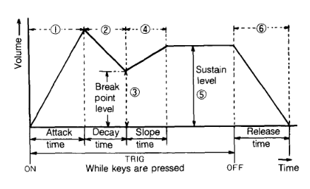
Here you can see the diagram I nicked from the user manual.
I always program my envelopes as little state-machines, going through the varous stages with each stage counting an 16-bit integer up or down depending
on what the stage represents. Thus it was easy to implement these extra 2 stages. One thing to keep in mind was that though the Decay still counts down
towards the breakpoint, the Slope counts
either up or down depending on the level of both the Breakpoint as the Sustain.
While programming this, I accidentally made an error which caused both the Decay as the Slope to count down past zero, thus overflowing the integer back to
65535. This created a really cool sounding repeating envelope, with the various stages repeating at different rates depending on the Decay and Slope setting.
I kinda, really, want to implement this as an optional feature in a future update. But for now the standard envelopes work perfectly fine.
The MG (LFO):
The MG is very basic, just an integer that counts up and down to create a triangle wave. Its value is centered to 2.5V on the DAC to prevent detuning.
There's also a value that counts up every time keys are being pressed, this value sets the amplitude of the MG thus acting as a smooth delay just as the original Poly800.
The Schematics
Again, there is a lot of ground and many sections to cover, so I'm going to go about it bit-by-bit again.
The Power:
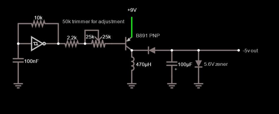
The power supplies in the original Poly800 were designed to generate +/-5V and 9V from just 6V DC, since the synth needed to be able to operate from a bunch of
batteries.
I have no interest in playing my synths on batteries, so the MK-III runs off a center-negative 9V wall adapter only. I use a 7805 voltage regulator for the +5V rail, and
a 40106 oscillator driving a power transistor driving an LC voltage-invertion circuit to generate the -5V. It has two trimmers to set the frequency (not shown on schematic) and
to set the output voltage. To prevent overvoltage (the 2069 VCF does not like that!) I added a zener diode.
The 9V from the wall adapter goes directly to the Chorus board, since the 9V is only ever used for the headphones amp on that board.
The 8-bit Bus and Latches:
The DAC and Sample-and-Hold:
The DCO:
The VCF:
The Potential Chorus Mods: