Yamaha E-70/EX-2
Gosh, this is truly an absolute beast of a... synthesizer, really. And that's the second time I've typed this phrase on this website...
So lets take a deep look at what makes this organ so enticing! And what mods one can do to it to make it into a full blown analog monster synthesizer that gets surprisingly close to a CS-80 on steroids.
Make sure to read this document too, it goes into deep detail about how P.A.S.S. works and the electronics involved.
Download the E-70 service manual.
List of E-70/EX-2 mods can be found here.
Tower of Power (E-70 in a rack) project: watch video series.
Marc's Son Of GX project demo: watch video.
THIS PAGE IS A WORK IN PROGRESS.
About the E-70 and EX-2
Yamaha has made a LOT of organs and synthesizers, the two often blending together in features and hardware. Yamaha had a tendency to test out their new tech in their organs before committing it to their synthesizers.
This is why I've always kept an eye on their organs, feeling an hunch that they may well hide some glorious polyphonic analog (or digital) synth hardware that usually is prohibitively expensive to acquire (looking at you CS synths).

To the left you can see the gorgeous fiberglass body version of the E-70 called the EX-2. It's exactly the same internally, but has a few different presets and lacks the internal amp + (leslie) speakers.
Marc Brasse kindly donated his E-70 to me, so I went from an hunch to a deep-dive and oh boy is there a lot of goodness in there.
He also helped build the case and frame for the Tower of Power.
Thanks Marc!
You may know Marc from his 'Son of GX' project, in which he expanded his E-70 with a bunch of new controls and a CSY-1 synth. Absolutely check out his website for more on that.
The Glorious Specs
Now what can this thing actually do that makes me rather hyped about it?
The specs:
- 11 additive organ voices with 10 layers of sine waves, plus 3 layers of attack sine waves. Also has a paraphonic IG00155 VCF,
- 1 additive pedal bass voice,
- 14 subtractive orchestra voices with IG00155 VCF (same as the IG00156 in the CS synths, but a bit more low end and slightly calmer resonance) and IG00151 VCA (same as used in the CS synths),
- 1 subtractive pedal bass voice with the same hardware as the orchestra,
- The ability to layer 7+7 voices (upper + lower keyboard), creating much more complex & layered sounds,
- The bass sounds can also be layered with the lower keyboard,
- 2 oscillators per voice (for detuning!) for both the organ as the orchestra. So you can get nice and thick sounds,
- Orchestra oscillators can be individually transposed in octaves from -1 to +3 for more layering,
- Oscillators for both organ as orchestra are digital but do things very differently for waveform generation than other digital synths of the 70's and 80's, evading typical issues with digitally generated audio,
- Technically multi-timbral as voice settings can be different between upper keyboard, lower keyboard and pedals,
- Digitally controlled but otherwise fully analog drums,
- And finally, of course: the ability to (easily) modify the daylights out of this thing :)
It's not a CS-80 by any means, but it has the potential to be a close sibling and perhaps in some ways is superior. It also has a lot in common with the GX-1, hence Marc's "Son of GX" project name.
So lets dive into the hardware and see what it is capable of.
All analysis is for the hardware in its stock form. If you want a comprehensive list of mods go here.
The Key Coder and adding MIDI
Because there's quite a lot of interest in adding MIDI to the E-series organs I decided to go into a bit more detail on how the "Key Coder" IC works. This information was nowhere to be found, aside from some fragmented bits on OrganForum and some vague explanations in the P.A.S.S. guide... So it took a bit of reverse engineering!
The Key Coder scans the key matrix and sends out 9 bits of data to the ABC and Channel Processor. It uses a bit of a different way of scanning and the data timing is quite specific.
The 9 bits are:
- KK1 & KK2: keyboard select. Determines if the note is on the Upper, Lower or Pedal.
- KB1-KB3: octave, uses an inverted binary value, see P.A.S.S. guide
- KN1-KN4: note, binary values but skips some, see P.A.S.S. guide
Finally there's a special "SL" reset command that clears all stored notes in the Channel Processor. This is for clearing out keys that have been released. This command is always send every 64 clock cycles, even if no keys are pressed.
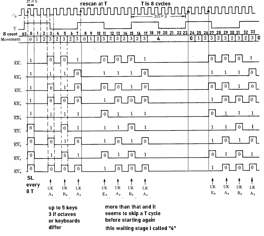
Here you can see a diagram from the P.A.S.S. guide that I've added a bunch of extra information to. Click to enlarge image.
The KC (Key Coder) IC works in 3 stages ("movement" in the picture), which are timed using a 27us clock "B" coming from the Channel Processor and a 215us clock "T" created by dividing the 27us clock 8 times.
- stage 0: "preparation time", not sure what happens internally but I imagine it sets internal counters and registers to default states,
- stage 1: it pulls all its note terminals to -15V, any octave terminals that are connected via a key press will thus also be pulled to -15V which the IC stores,
- stage 2: memorized octave terminals now get pulled up to 0V and now any note terminals that are connected via key press will get pulled up to 0V thus they are stored as well,
- stage 3: now that the data has been collected the KC sends 9 bits of key data out every 27us clock cycle, but it will skip a cycle if subsequent key data is not in the same octave, this skip is done by reverting to stage 2. I think it actually needs to do this to switch to the next octave (pull up to 0V) before it can store and send out the actual note data of that octave.
- once the data has been output, the KC waits for the 215us "T" clock to rise before starting the whole process over again from stage 0.
For further details on how all the channel assign in the Channel Processor, etc works I highly recommend reading the P.A.S.S. guide linked in the intro of this page.
The Digital Oscillators and Waveform Generators

P.A.S.S stands for Pulse Analog Synthesizing System, often abbreviated to 'System' by Yamaha. It's a digital system that turns a series of serial pulses into analog waveforms and envelopes using some very interesting techniques.

The specific P.A.S.S. system used in the E70/EX-2 is the 'PASS-VCF System', which combines additive synthesis and subtractive synthesis for the various flute and orchestra tones.
To the left you can see a block diagram of this system, click the image to make it bigger.
The Flute tones use a combination of sine waves, but the Orchestra tones use square, pulse and sawtooth.
Yamaha faced the problem that their design for their new digital oscillators would take up a lot of real-estate if they wanted full polyphony. Even more so for an organ, because there's two keyboards that both need polyphony.
Remember that this is the early 70's and there was no luxury of microcontrollers. Nowadays you could stuff the entire E-70 in something the size of your palm...
Instead of having a separate set of ICs per voice (up to 12 total), Yamaha came up with a clever system that only needs hardware for 1 voice by processing all voices serially.
The actual digital processing is a "serial channel" system that takes place at 1MHz , since there's up to 12 channels that need to be processed in series so extra speed was required. Processing everything in series means only 1 set of IC's is needed to process everything, instead of 12 sets! Each channel is processed in 1 microsecond, thus totaling at 12 microseconds for all voices.
Now we're getting into the meat of this thing: digital oscillators, oh no the heresy! But do not fret...
Using P.A.S.S. means digital oscillators but Yamaha did some tricks to avoid aliasing and other typical digital issues from those days, making it sound a lot better than many other digital synths of the time.

There's no set samplerate and no waveform ROM: instead a custom multi-stage resistor-ladder DAC is used which already has the waveform "baked in", if you will.
This means the digital phase counter directly drives the DAC with the "sample rate" being a maximum of 8192 times the note frequency i.e. A440 would be 3.6MHz for the 1st bit, with the 14th bit oscillating at 440Hz and the 16th at 110Hz.
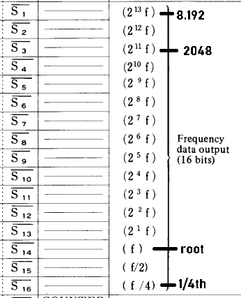
The YM21400 "wave counter" could be seen as a programmable digital oscillator, that produces 16 "octaves" of square waves at a frequency set by a 14-bit value from earlier stages of the digital system (controller and frequency ROM).
Binary counters are functionally the same as octave dividers, hence my way of wording this.
11 of these 16 octaves are used per waveform generator, with multiple generators used for the organ tones, their inputs connected to different octaves to make it easy to generate all the organ footages at once.

To the left you can see the sine waveform generator for the organ tones (named 'Flute').
You can see two resistor ladders are used, to get the full 11 bits (2048 steps) range. There's also external opamps for further buffering.
Another trick the DAC has is that its minimum and maximum voltage are externally controlled by an analog CV (named IL and IH). This way lowering the volume of the waveform does not require its bit depth to be lowered and doesn't cause degradation of the generated waveform, which was a very common issue in digital audio back in the day. It's something you can still hear in very cheap (kids) keyboards nowadays.
Interestingly the waveform generators for the orchestra are slightly more complex as they allow for interpolation. Digitally generated audio had one more issue that needed tackling: aliasing in waveforms with high harmonic overtone content.
The sine waves of the flutes don't have any harmonic overtones, so there's no issues. However the orchestra uses square, pulse and sawtooth waveforms which are rich in overtones and thus can cause all sorts of nasty noises when playing high notes.
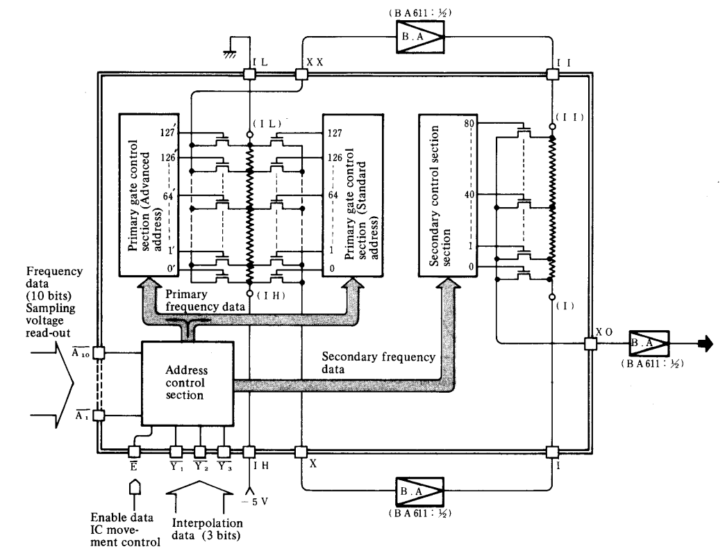
There's the same two resistor ladders, but there's additional control circuitry that will generate interpolation address data, essentially smoothing the waveform out like a digital low-pass filter. This interpolation can go so far it can even turn the waveforms into almost-sine waves (see diagram below).
The way this is used is that the higher the note being played the stronger the interpolation and thus the weaker the harmonic overtones get.

Two important mentions need to be made here:
1. The frequency ROMs, WaveCounters and waveform generators are all doubled up. So there's a full 2 oscillators per voice for both the organ as the orchestra. This is needed because the 'Celeste' function detunes the second oscillator to create the effect. This also means it is possible to go a step further with mods and set the second oscillator to be an octave lower or higher for even fatter layering.
2. Because all of the digital stuff is done in sequence, through 12 channels in series, there's some distribution and sample & hold circuitry necessary. Again: the whole system runs at 1MHz, thus the true samplerate of the system at this point becomes either 1MHz/12 = 83Khz. Luckily this samplerate is plenty high so there won't be any issues with high frequency content passing through, with the Nyquist frequency being at 41KHz.
To eliminate any clock/samplerate noises from bleeding through a low-pass filter at around 27KHz is used before the final analog mixing stage. This means there's the full human hearing range in bandwidth available.

The Analog Glory (VCF, VCA)
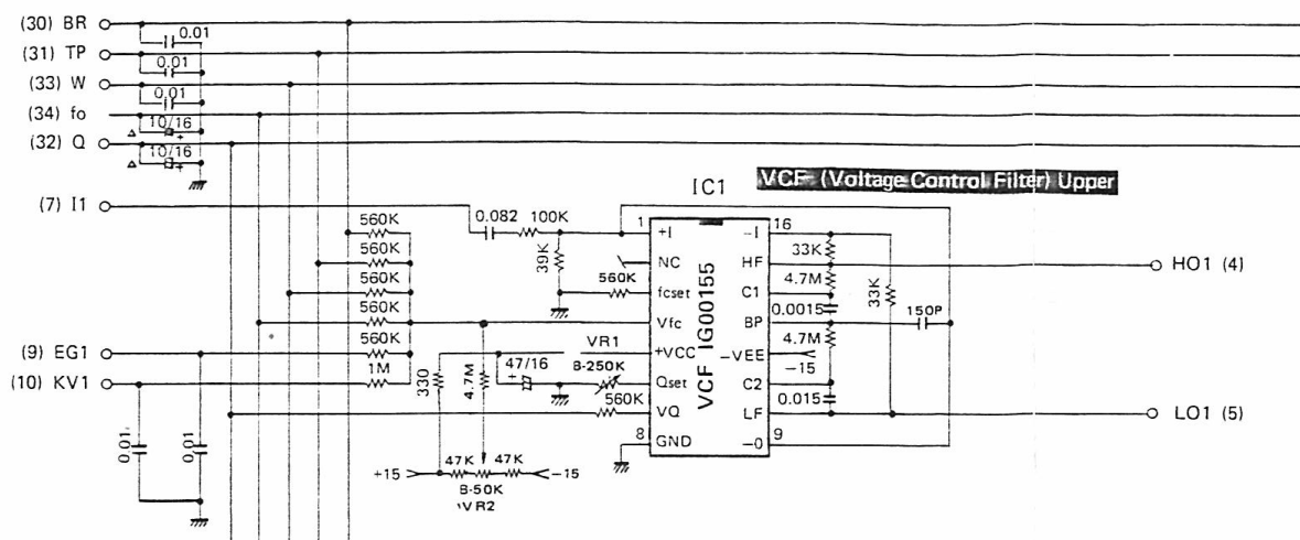
This is the part where the commonly seen claim of "turn your E-70 into a CS-80" becomes somewhat true! Below you can see a block diagram of a single voice, sans the digital section.

The IG00155 used in the organs is the same as the IG00156 in the CS synths, but has a slightly "calmer" resonance and more low-end, which makes them very interesting filters. Personally at least I prefer these specs over loads of resonance but too much thinning out. Though the IG00155 of course still thins out at high resonance.
This isn't a problem however as there's an entire additive sine-wave synth in the organ, namely the flutes, that allows you to fill up the low end if needed.
Having heard Marc's Son Of GX in action I was surprised how full & rich the sounds are. The basses are absolutely thunderous.
I'm not sure how this compares to a CS-80, but a comparison between the two VCF IC's would definitely be interesting...
Either way: there's TWO of these bad boys per voice and each does both high-pass, low-pass as band-pass. This means you can have different filter modes for your voices which makes things very flexible. The IG00155 does have its own dedicated output for the various modes, but Yamaha needed more control over the separate HP and LP cutoff and resonance settings, so two ICs are used per voice. I imagine with some modding to expose all three outputs per IC you could get some very interesting results.
This means there's 30 of these in the E-70! 14 for upper, 14 for lower and 2 for the pedals. CS synths eat your heart out.

To the left you can see the frequency versus control voltage graph from the P.A.S.S. manual.
The filters are configured so that with the CV halfway the cutoff frequency sits at 800Hz. As you can see there's quite a large range on the filters, from 25Hz all the way to 15000Hz.
For the control voltages there are full ADSR envelopes with initial level + attack level, plus manual controls plus... keyboard tracking! Nice.
The resonance is also voltage controlled, per filter, for even more fun.
There's also a VCA per voice. This part is pretty standard, just a VCA to control amplitude controlled by an envelope. As they do. This is the exact same VCA as used in the CS synths.
The VCA's are configured to allow for mixing of all 14 orchestra + 1 pedal voice without clipping.
Control voltage is once again from an ADSR + initial level + attack level envelope
The Flute Envelopes
There are two types of envelopes in the E-70: for the flutes and for the orchestra.
Whereas the orchestra envelopes are ADSR with some extras the flute ones are simpler, but with multiple modes, plus some special functionality for repeating.
There are two envelope generators, with different configurations, for the attack and normal flutes. They can possibly be modded to allow for full functionality on both. At their core they are the same ASR design:

There are resistor dividers involved, it's very similar to the waveform generators in how the envelope is generated, including analog CV for voltage levels. However there are internal counters for each envelope stage, driven by external VCOs. More details on this system below in the Orchestra envelopes section.
In the above example you can see it counts up to 127 for the attack, holds it at 127 for sustain and then counts back down to 0 for release.

The Flute envelopes have an extra feature: modes.
These are sort-of presets that change the behavior of the envelope. To the left you can see a list of the various modes and illustrations on how it changes the envelope.
The Flute organ sounds usually use the Sustain Mode, whereas the attack sounds and some presets like Vibraphone and Chimes use the Percussive Modes.
The attack can be set to repeat, switching the Percussive Mode to its repeating variant. The rate of repeat is determined by the decay.
The Orchestra Envelopes
These are a doozy and very mod-able. The envelopes aren't simple either, so plenty of fun can be had here.
Again there are resistor dividers involved, it's very similar to the waveform generators in how the envelope is generated, including analog CV for voltage levels. The control circuitry is different however.
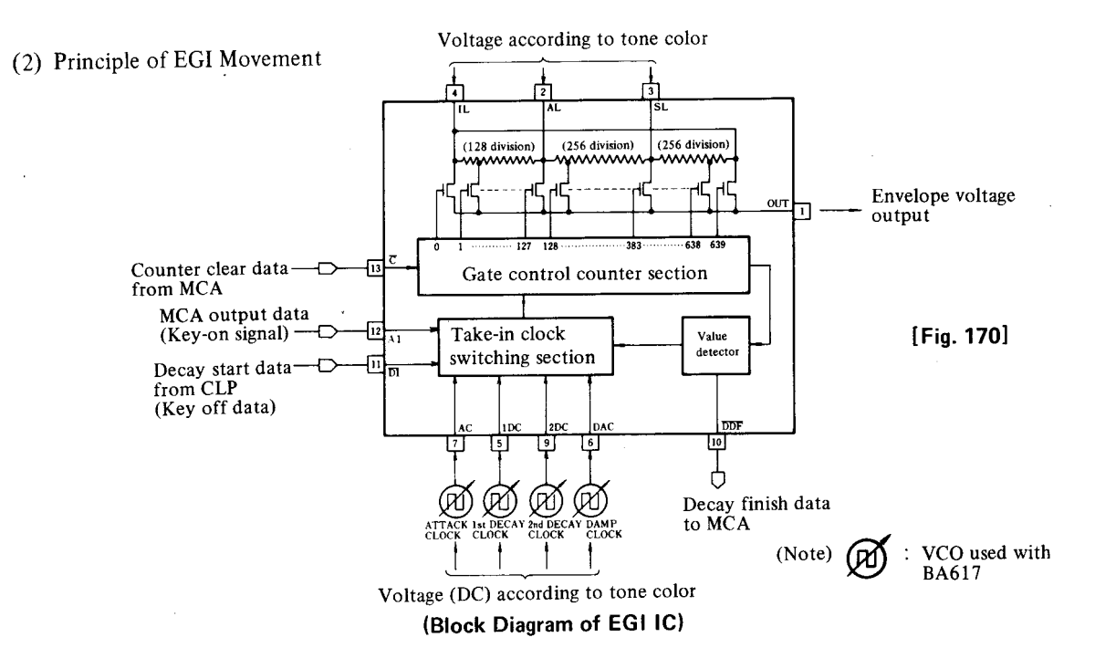
The first surprising thing is that the timings are all controlled via analog VCOs. There are many, many, BA617 VCOs in the E-70. They are indicated in the left diagram by the square wave in the circle, with an arrow through it. The DC control voltages are all from -15V to GND, from slowest to fastest.
Below you can see one of the many VCOs as a schematic, of the upper keyboard VCF attack.

As you can see to the left there are 4 clocks per generator, plus 3 level control voltages (at the top of the diagram) for:
- Initial Level, the voltage the envelope starts at;
- Attack Level, the voltage the attack stage raises or lowers (!) to in 128 steps;
- Sustain Level, as the name implies the voltage the decay stage lowers or raises (!) to in 256 steps, and stays at whilst the key is pressed;
- The release stage is also 256 steps.

There is also a "damp(er) clock" which is for a different release them when a key is released whilst the envelop is still in the decay stage.
In the graph to the left you can see this effect visually, the "DAC" section is the damper clock.
Interestingly this creates a decay-release-release, which is used for the piano for example.
Usually the damper release stage is faster than the normal release.
The clocks of the various stages can go anywhere between 25Hz and 80KHz, with some variations in the actual range depending on external component values used. Generally the range is very large and thus gives a lot of flexibility.
For example, the attack for upper and lower VCF's:
- the fastest attack is 80KHz/128 steps = 1.6ms;
- the slowest attack is 115Hz/128 steps = 1123ms a.k.a. just over a second.
The release, being 256 steps, but with different timing range:
- fastest release: 40KHz/256 steps = 6.4ms;
- slowest release: 30Hz/256 steps = 8547ms a.k.a. over 8 seconds.
Of course you could adjust the trimmers on the VCOs to change these timings to your preference. I've yet to test if the actual range can be extended easily, though adding a switch for 2 different ranges is always an option.
Analog Drums
TODO
Drums are all analog wooo~

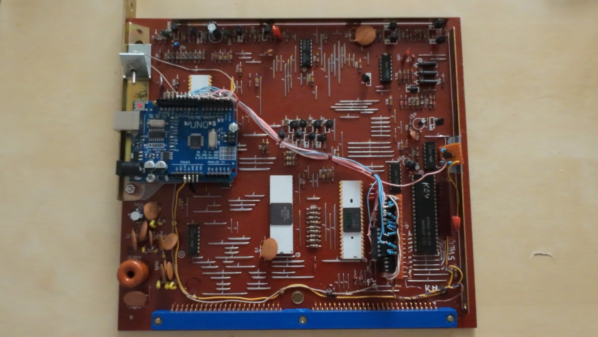
The insides of my E-70 and the Tower of Power (E-70 in rack format)
Here's a bunch of pictures I took, whilst taking the E-70 apart to build the Tower of Power.